InfraDrone Engine Pipeline
How InfraDrone turns drone imagery into structured road-damage records with detection, segmentation, skeletonization, branch merging, and measurement.
The InfraDrone engine is an image-processing and machine-learning pipeline for detecting road damage from drone or camera imagery and converting the results into structured damage records. The engine starts with a raw frame, cleans it up for model inference, detects candidate damage regions, segments the exact crack or pothole shape, and then converts those model outputs into structured damage records.
The important part is that the engine does not stop at detection. It also uses segmentation and post-processing to estimate crack geometry, split and merge branches, classify the crack subtype, and calculate measurements like length, thickness, and area.
The Pipeline
At a high level, the engine has nine stages:
| Step | Purpose |
|---|---|
| 1 | Load a frame from the input queue or image source. |
| 2 | Preprocess the image for road-surface contrast and model input size. |
| 3 | Run YOLO detection to find cracks and potholes as bounding boxes. |
| 4 | Crop each detected region so segmentation only sees the relevant area. |
| 5 | Run YOLO segmentation to create binary masks for each damage region. |
| 6 | Skeletonize the masks and analyze crack branches. |
| 7 | Merge branch fragments that are close and directionally aligned. |
| 8 | Measure dimensions and classify the damage subtype. |
| 9 | Return a structured damage record for downstream reporting. |
In code, the top-level engine wires together DetectionEngine and SegmentationEngine. The current implementation can be summarized like this:
Preprocessing
The preprocessing step makes road texture easier for the models to read. A raw frame can have glare, shadows, compression noise, and inconsistent resolution, so each image is normalized before inference.
The current preprocessing function does three things:
- resizes the image to the model input size;
- applies CLAHE in LAB color space to improve local contrast;
- applies bilateral filtering to denoise while preserving edges.
Cracks are thin, low-contrast structures, so increasing local contrast before detection and segmentation helps the model see the features that matter. So the post-processing allows the model to detect damage more accurately.
Detection
The detection stage uses a YOLO model trained to find two high-level classes: crack and pothole.
For a preprocessed image, the detector returns bounding boxes with coordinates, confidence, and predicted damage type. Detections below the configured confidence threshold are removed. The remaining boxes are cropped from the image and passed into segmentation.
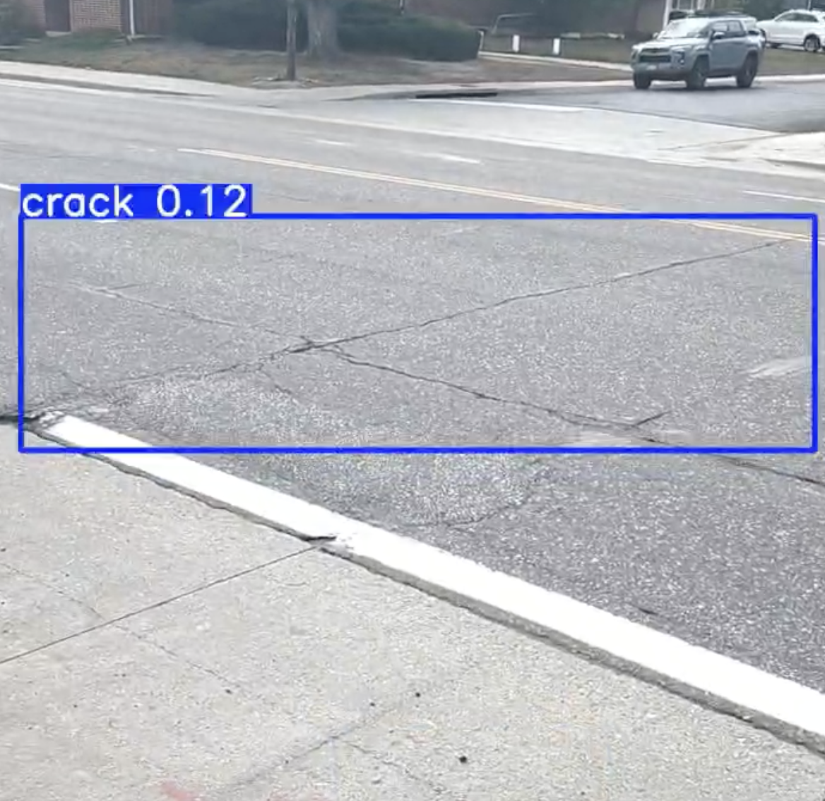
This two-model design keeps the segmentation problem smaller. Instead of asking the segmentation model to understand the whole image, the detector narrows the input down to likely damage regions first.
Segmentation
The segmentation model returns a binary mask for each detected damage crop. Each mask is thresholded and skeletonized. The mask keeps the full damaged area, while the skeleton reduces the crack to a one-pixel-wide centerline.
That centerline is much easier to reason about because crack length, direction, endpoints, and branches become graph-like properties instead of raw mask properties.
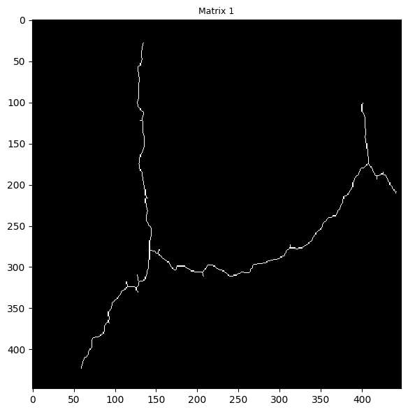
The full segmentation mask is reduced to a one-pixel-wide centerline while preserving the crack shape.
Branch Detection
Once the crack is skeletonized, the engine searches for branch points and endpoints. A branch point is a skeleton pixel with at least three neighboring skeleton pixels within its 8-connected neighborhood.
The engine dilates the branch-point region, removes it from the skeleton, and labels the remaining connected components. Each component becomes a candidate branch. Very short components are removed so tiny artifacts do not become reported cracks.
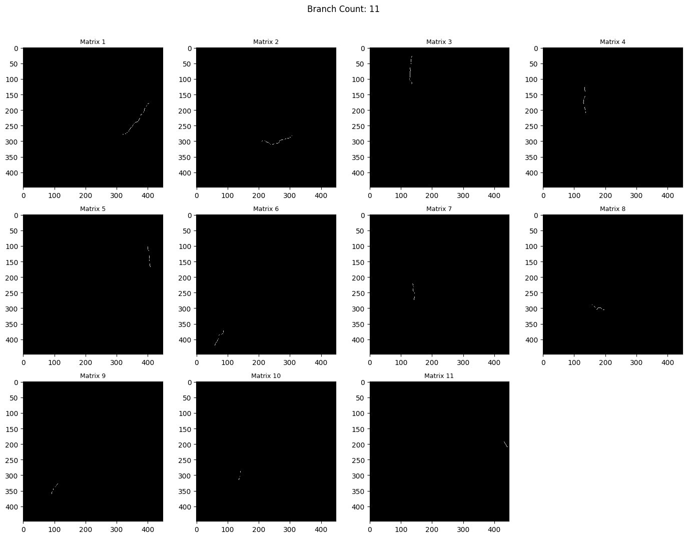
Junction pixels are removed so connected-component labeling can isolate each branch.
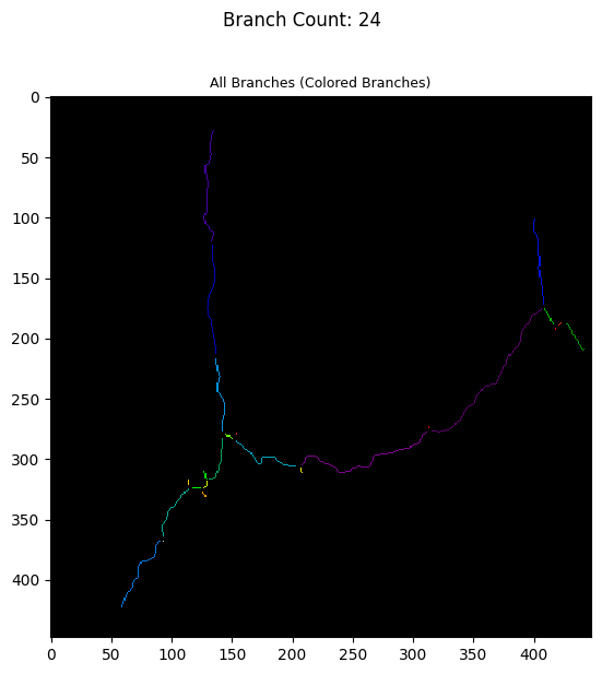
Each surviving component is treated as a separate branch candidate.
Branch Angles and Merging
Cracks often get split into multiple pieces because segmentation masks are imperfect. So the engine reconnects branch fragments when they are close together and point in roughly the same direction.
For each branch, the overall axis angle is estimated from the farthest pair of endpoints. The angle is treated as undirected, so 0 degrees and 180 degrees are equivalent. For local merge checks, the engine also estimates endpoint direction with PCA over nearby skeleton pixels. That gives a better tangent estimate at the endpoint than using the whole branch.
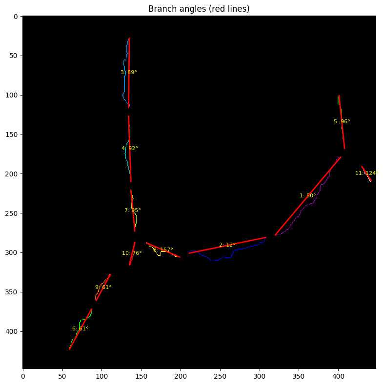
The red guide lines show the direction used for classification and merge checks.
Two branches can merge if their closest endpoint distance and local angle difference are below the configured thresholds. When more than one pair is eligible, the engine chooses the lowest score:
score = endpoint_distance + angle_differenceThe selected pair is merged by drawing a bridge between the closest endpoints, recomputing the skeleton, and repeating until no more pairs qualify.
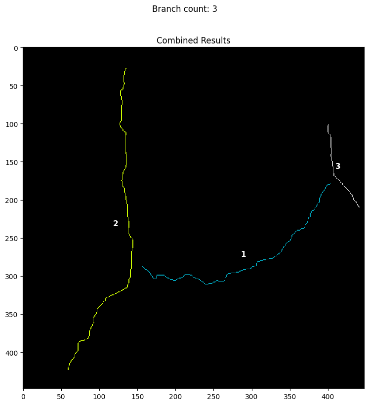
The numbered branches are the geometry passed into measurement and subtype classification.
Measurements
The final branch mask and skeleton are converted into physical measurements. Right now the engine stores these in pixel units unless a real-world scale ratio is configured.
Thickness is estimated with a distance transform. For each skeleton pixel, the distance transform gives the distance to the nearest mask boundary. Doubling that value gives a local width estimate, and averaging across the skeleton gives the crack’s average thickness.
Length is currently estimated as the Euclidean distance between the farthest endpoint pair. That works well for mostly straight branches. In the future I’m planning on measuring length along the skeleton path itself.
Area is the number of foreground pixels in the mask. If the engine has a pixel-to-real-world conversion ratio, thickness, length, and area can be scaled into centimeters or inches.
Subtype Classification
After the geometry is measured, the engine assigns a crack subtype. The current rule is intentionally explainable:
- if the branch network has many connections, classify it as alligator cracking;
- otherwise classify by orientation angle;
- branches above the angle threshold are longitudinal;
- branches below the angle threshold are transverse.
The subtype comes from skeleton shape and image orientation instead of hiding the decision in another model.
Output Record
Each final result becomes a Damage object. The record includes:
- a unique ID;
- the final mask and skeleton;
- the damage type, either crack or pothole;
- confidence;
- thickness, length, and area;
- subtype;
- stress range;
- number of branch connections;
- severity placeholder.
The severity field is currently set to zero. The planned direction is to combine measured damage geometry with road-class stress information and fatigue-growth modeling.
Current Limitations
The current pipeline works as an end-to-end analysis path, but a few areas still need to be tightened:
- severity scoring needs to be implemented;
- length is measured endpoint-to-endpoint instead of along the skeleton path;
- real-world pixel scale will end up coming from camera altitude and focal length.
Why This Shape Matters
InfraDrone’s pipeline is built around a simple split: use detection to find where damage probably is, then use segmentation and image processing to understand what that damage actually looks like.
Current solutions for road damage detection struggle with getting meaninful measurements from detections. The goal of this pipeline is to help solve that problem.